How to interface Arduino with
a Playstation game-port controller
A Playstation controller has two analog mini sticks (Dualshock and DualShock2 only), 12 pressure sensitive buttons (Dualshock 2 only) and two digital buttons. All these inputs can be made available to the Arduino via only 4 pins (three of which can be shared with other functions, if planned carefully).
Playstation controllers are cheap. There widely available (from brand new ones in stores to used ones at garage sales).
Cordless versions make it easy to remote control your Arduino-based project.
Very little external hardware is needed.
I needed something to control this model excavator.
The Playstation gameport uses a rather sophisticated protocol built on top of a very simple and common serial interface: SPI. This synchronous serial interface uses four lines: a clock (sent by the Arduino), a data input (called MISO), a data output (MOSI) and a select (sometimes called SS or ATT). This interface is byte oriented and a basic transfer consist of an exchange of eight bits. There are several parameters that need to be agreed upon before a successful link can be established (speed, data order, clock polarity and active clock edge). However, you don't need to worry about these too much as the library sets up the Arduino to match the format used by the Playstation.
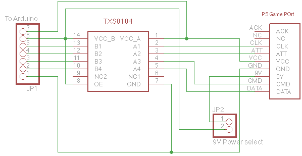
There is one difference between Arduino and a Playstation: while Arduino runs at 5V, the Playstation (and its peripherals) are designed to run at 3.3V. Some people have successfully run some of these game pads at 5V, however I am not sure how reliable such a setup would be for the long term. As the drawing below shows, I decided to use a special chip (the TXS0104, Available from Digi-Key) to adjust the logic levels between the Arduino and the Playstation plug. This chip is very easy to use: just power VCCb at 5V and VCCa at 3.3V and you are done! Please note that a previous version of this page had VCCa and VCCb reversed. Thanks to Joonas for pointing out my error. Each of the four channels is fully bi-directional without a need to select the direction. If you are curious about its internals, have a look at the data-sheet here.
Of course, a transistor based level shifting circuit would also work, keeping in mind that the clock runs at 500KHz.
The following table shows how to connect the Arduino to the level shifting board shown above.
|
Arduino connections |
Signal description |
Level shifter connections |
|---|---|---|
|
GND |
Ground |
1 |
|
5V |
5Volt supply |
6 |
|
3.3V |
3.3 Volt supply |
7 |
|
12 |
Data (from controller to Arduino) |
2 |
|
11 |
Command (from Arduino to controller) |
3 |
|
10 |
Chip select (also called ATT) |
4 |
|
13 |
Clock |
5 |
Update (November 2011): There are now Arduino boards that run at 3.3V. If you use one of these, you can skip the whole level shifter circuit.
One item that may appear to be hard to get is a game-port connector. One way to get one is to buy a game-port extension cord, cut it in half and using an Ohm-meter find out how to wire it. The plug in some extension cords is built in such way that it is possible to extract the plug proper from its outer casing (sometimes called “over-molding”). With some care it is possible to extract a plug that is ready to be mounted on a PCB.
You only need two function calls to use this library: Init_PSX() and Poll_PSX(). Simply call Init_PSX() in your setup() function then call Poll_PSX() in your loop() function.
There is one important detail that you need to keep in mind: Poll_PSX() must not be called more often than once every 16mS or less often than 2000mS. Calling it at a faster rate may cause some devices to malfunction (in particular the wireless ones). If more than two seconds elapses between calls, the device will stop providing analog sticks and pressure button data. If your application requires that you call poll_PSX() less often than two seconds, then call Init_PSX() before poll_PSX(). This method has not been fully tested!
Function details:
Init_PSX(): no arguments, no return value.
Poll_PSX(byte Big_Motor_Value, boolean Small_Motor_Value): Big_Motor_Value controls the large vibration motor. A value of 0 stops it and other values sets its speed (in practice, any value below about 100 will not provide enough power to run the motor). Small_Motor_Value: if true the small vibration motor runs. If falls it is stopped.
The data received from the device is placed in an array called PS_Data[]. The following definitions are provided to make accessing the various fields more readable.
#define PS_DIGI_BUTTONS_0 0
#define PS_DIGI_SELECT_BUTTON_OFFSET 0
#define PS_DIGI_SELECT_BUTTON_MASK 0x01
#define PS_DIGI_L3_BUTTON_OFFSET 0
#define PS_DIGI_L3_BUTTON_MASK 0x02
#define PS_DIGI_R3_BUTTON_OFFSET 0
#define PS_DIGI_R3_BUTTON_MASK 0x04
#define PS_DIGI_START_BUTTON_OFFSET 0
#define PS_DIGI_START_MASK 0x08
#define PS_DIGI_UP_BUTTON_OFFSET 0
#define PS_DIGI_UP_BUTTON_MASK 0x10
#define PS_DIGI_RIGHT_BUTTON_OFFSET 0
#define PS_DIGI_RIGHT_BUTTON_MASK 0x20
#define PS_DIGI_DOWN_BUTTON_OFFSET 0
#define PS_DIGI_DOWN_BUTTON_MASK 0x40
#define PS_DIGI_LEFT_BUTTON_OFFSET 0
#define PS_DIGI_LEFT_BUTTON_MASK 0x80
#define PS_DIGI_BUTTONS_1 1
#define PS_DIGI_L2_BUTTON_OFFSET 1
#define PS_DIGI_L2_BUTTON_MASK 0x01
#define PS_DIGI_R2_BUTTON_OFFSET 1
#define PS_DIGI_R2_BUTTON_MASK 0x02
#define PS_DIGI_L1_BUTTON_OFFSET 1
#define PS_DIGI_L1_BUTTON_MASK 0x04
#define PS_DIGI_R1_BUTTON_OFFSET 1
#define PS_DIGI_R1_BUTTON_MASK 0x08
#define PS_DIGI_TRIANGLE_BUTTON_OFFSET 1
#define PS_DIGI_TRIANGLE_BUTTON_MASK 0x10
#define PS_DIGI_CIRCLE_BUTTON_OFFSET 1
#define PS_DIGI_CIRCLE_BUTTON_MASK 0x20
#define PS_DIGI_CROSS_BUTTON_OFFSET 1
#define PS_DIGI_CROSS_BUTTON_MASK 0x40
#define PS_DIGI_SQUARE_BUTTON_OFFSET 1
#define PS_DIGI_SQUARE_BUTTON_MASK 0x80
#define PS_RX_OFFSET 2
#define PS_RY_OFFSET 3
#define PS_LX_OFFSET 4
#define PS_LY_OFFSET 5
#define PS_RIGHT_PRESSURE 6
#define PS_LEFT_PRESSURE 7
#define PS_UP_PRESSURE 8
#define PS_DOWN_PRESSURE 9
#define PS_TRIANGLE_PRESSURE 10
#define PS_CIRCLE_PRESSURE 11
#define PS_CROSS_PRESSURE 12
#define PS_SQUARE_PRESSURE 13
#define PS_L1_PRESSURE 14
#define PS_R1_PRESSURE 15
#define PS_L2_PRESSURE 16
#define PS_R2_PRESSURE 17
The following example reads the pad, uses the four axes of the ministicks to drive four PWM on the Arduino and the pressure value of L1 to drive the gamepad's large vibration motor. The start button controls the gamepad's small vibration motor. Please note that I have not tested the vibration motor part of the code myself. I wrote this library based on the information found here and here. The initial idea came from this page.
/*
* PS_Demo
* by David Wegmuller www.wegmuller.org
*
* Emulates a Playstation 2 game port. Use the game pad data to control four
* PWMs on the Arduino and the gamepad's own vibration motors.
*/
//#define ENABLE_SERIAL_DEBUG //uncomment for debug
#define DATAOUT 11//MOSI
#define DATAIN 12//MISO
#define SPICLOCK 13//sck
#define SLAVESELECT 10//ss
// Setup all the PWMs in a safe mode (i.e. all motors off)
void Init_PWM(void)
{
// Start the PWMs at 0%
analogWrite(3, 0);
analogWrite(5, 0);
analogWrite(6, 0);
analogWrite(9, 0);
}
//-----------------------------------------------------------------------------------------
// Begin Playstation library
//-----------------------------------------------------------------------------------------
// Data packet from the PS interface.
byte PS_Data[18];
#define PS_DIGI_BUTTONS_0 0
#define PS_DIGI_START_MASK 0x08
#define PS_DIGI_BUTTONS_1 1
#define PS_RX_OFFSET 2
#define PS_RY_OFFSET 3
#define PS_LX_OFFSET 4
#define PS_LY_OFFSET 5
#define PS_RIGHT_PRESSURE 6
#define PS_LEFT_PRESSURE 7
#define PS_UP_PRESSURE 8
#define PS_DOWN_PRESSURE 9
#define PS_TRIANGLE_PRESSURE 10
#define PS_CIRCLE_PRESSURE 11
#define PS_CROSS_PRESSURE 12
#define PS_SQUARE_PRESSURE 13
#define PS_L1_PRESSURE 14
#define PS_R1_PRESSURE 15
#define PS_L2_PRESSURE 16
#define PS_R2_PRESSURE 17
// Exchange one byte over SPI (with wait for completion)
byte SPI_Exchange(byte Data)
{
SPDR = Data; // Write the outgoing data to the SPI
while(0 == (SPSR & (1 << SPIF)))
{
#ifdef ENABLE_SERIAL_DEBUG
Serial.println(SPSR,HEX);
#endif
} // Wait for the transfer to complete
return SPDR; // Return the data received over SPI
}
// Setup the hardware SPI and enable rumble and analog functions on the gamepad
void Init_PSX()
{
byte clr;
// Set the chip select (SS) as output high
pinMode(SLAVESELECT, OUTPUT);
pinMode(DATAOUT, OUTPUT);
pinMode(DATAIN, INPUT);
pinMode(SPICLOCK,OUTPUT);
pinMode(SLAVESELECT,OUTPUT);
digitalWrite(SLAVESELECT, HIGH);
//interrupt disabled,spi enabled,lsb 1st,master,clk high when idle,
//sample on leading edge of clk,system clock/8 rate (500Kbit/S)
SPCR = (1<<SPE)|(1<<MSTR)|(1<<SPR1)|(1<<CPOL)|(1<<CPHA)|(1<<DORD);
SPSR = (1<<SPI2X);
clr=SPSR;
clr=SPDR;
delay(10);
// Enter escape mode
digitalWrite(SLAVESELECT, LOW); // Select the pad.
delayMicroseconds(10);
clr = SPI_Exchange(0x01);
delayMicroseconds(20);
clr = SPI_Exchange(0x43); // Special polling command
delayMicroseconds(20);
clr = SPI_Exchange(0x00);
delayMicroseconds(20);
clr = SPI_Exchange(0x01); // Enter escape mode
delayMicroseconds(20);
clr = SPI_Exchange(0x00);
delayMicroseconds(20);
digitalWrite(SLAVESELECT, HIGH); // de-select the pad.
delay(16); // wait 16mS before the next poll.
// Set analog mode mode
digitalWrite(SLAVESELECT, LOW); // Select the pad.
delayMicroseconds(10);
clr = SPI_Exchange(0x01);
delayMicroseconds(20);
clr = SPI_Exchange(0x44); // Set major mode
delayMicroseconds(20);
clr = SPI_Exchange(0x00);
delayMicroseconds(20);
clr = SPI_Exchange(0x01); // Enter dualshock mode
delayMicroseconds(20);
clr = SPI_Exchange(0x03); // Unknown parameter...
delayMicroseconds(20);
clr = SPI_Exchange(0x00);
delayMicroseconds(20);
clr = SPI_Exchange(0x00);
delayMicroseconds(20);
clr = SPI_Exchange(0x00);
delayMicroseconds(20);
clr = SPI_Exchange(0x00);
delayMicroseconds(20);
digitalWrite(SLAVESELECT, HIGH); // de-select the pad.
delay(16); // wait 16mS before the next poll.
// Enable the vibration function
digitalWrite(SLAVESELECT, LOW); // Select the pad.
delayMicroseconds(10);
clr = SPI_Exchange(0x01);
delayMicroseconds(20);
clr = SPI_Exchange(0x4d); // Set up actuator mapping
delayMicroseconds(20);
clr = SPI_Exchange(0x00);
delayMicroseconds(20);
clr = SPI_Exchange(0x00); // small motor
delayMicroseconds(20);
clr = SPI_Exchange(0x01); // large motor
delayMicroseconds(20);
clr = SPI_Exchange(0xff); // Next four are disabled
delayMicroseconds(20);
clr = SPI_Exchange(0xff);
delayMicroseconds(20);
clr = SPI_Exchange(0xff);
delayMicroseconds(20);
clr = SPI_Exchange(0xff);
delayMicroseconds(20);
digitalWrite(SLAVESELECT, HIGH); // de-select the pad.
delay(16); // wait 16mS before the next poll.
// Now switch the controller into pressure sensitive mode
digitalWrite(SLAVESELECT, LOW); // Select the pad.
delayMicroseconds(10);
clr = SPI_Exchange(0x01);
delayMicroseconds(20);
clr = SPI_Exchange(0x4F);
delayMicroseconds(20);
clr = SPI_Exchange(0x00);
delayMicroseconds(20);
clr = SPI_Exchange(0xff);
delayMicroseconds(20);
clr = SPI_Exchange(0xff);
delayMicroseconds(20);
clr = SPI_Exchange(0x03);
delayMicroseconds(20);
clr = SPI_Exchange(0x00);
delayMicroseconds(20);
clr = SPI_Exchange(0x00);
delayMicroseconds(20);
clr = SPI_Exchange(0x00);
delayMicroseconds(20);
digitalWrite(SLAVESELECT, HIGH); // de-select the pad.
delay(16); // wait 16mS before the next poll.
}
// Get one data packet via SPI
void Poll_PSX(byte Big_Motor_Value, boolean Small_Motor_Value)
{
byte Loop_Cnt;
byte clr;
// Set the gamepad into pressure mode. Note that from this point on, we
// must sample the pad at least once every two seconds or it will leave
// pressure mode.
digitalWrite(SLAVESELECT, LOW); // Select the pad.
delayMicroseconds(10);
clr = SPI_Exchange(0x01);
delayMicroseconds(20);
clr = SPI_Exchange(0x42);
delayMicroseconds(20);
clr = SPI_Exchange(0x00);
for(Loop_Cnt = 0; Loop_Cnt < 18; Loop_Cnt++)
{
delayMicroseconds(20);
switch(Loop_Cnt)
{
default:
PS_Data[Loop_Cnt] = SPI_Exchange(0x00);
break;
case 1:
PS_Data[Loop_Cnt] = SPI_Exchange(Big_Motor_Value);
break;
case 0:
if(Small_Motor_Value)
{
PS_Data[Loop_Cnt] = SPI_Exchange(255);
}
else
{
PS_Data[Loop_Cnt] = SPI_Exchange(0);
}
break;
}
}
digitalWrite(SLAVESELECT, HIGH); // de-select the pad.
// Invert the digital buttons (they are active low in the PSX!?!)
PS_Data[ PS_DIGI_BUTTONS_0] ^= 255;
PS_Data[ PS_DIGI_BUTTONS_1] ^= 255;
}
//-----------------------------------------------------------------------------------------
// End Playstation library
//-----------------------------------------------------------------------------------------
//-----------------------------------------------------------------------------------------
// Begin sample code
//-----------------------------------------------------------------------------------------
void setup() {
#ifdef ENABLE_SERIAL_DEBUG
Serial.begin(9600);
#endif
Init_PSX();
Init_PWM();
}
void loop() {
delay(16); // Don't poll the gamepad too often...
Poll_PSX(PS_Data[PS_L1_PRESSURE], PS_Data[PS_DIGI_START_BUTTON_OFFSET] & PS_DIGI_START_BUTTON_MASK);
analogWrite(3, PS_Data[PS_LX_OFFSET]);
analogWrite(5, PS_Data[PS_LY_OFFSET]);
analogWrite(6, PS_Data[PS_RX_OFFSET]);
analogWrite(9, PS_Data[PS_RY_OFFSET]);
}